Ride Control Accumulator Test & Charge

Personal injury can result from hydraulic oil pressure and hot oil.
Hydraulic oil pressure can remain in the hydraulic system after the engine has been stopped. Serious injury can be caused if this pressure is not released before any service is done on the hydraulic system.
Make sure all of the attachments have been lowered and the oil is cool before removing any components or lines. Remove the oil filler cap only when the engine is stopped, and the filler cap is cool enough to touch with your bare hand.
Sudden movement or accidental starting of the machine can cause personal injury or death, perform the following:
- Park the machine on a smooth, level surface.
- Lower the bucket and/or attachments to the ground and engage the parking brake.
- Stop the engine and remove the key.
- Block the wheels and install the steering frame lock.
Notice
Care must be taken to ensure that fluids are contained during performance of inspection, maintenance, testing, adjusting and repair of the product. Be prepared to collect the fluid with suitable containers before opening any compartment or disassembling any component containing fluids.
Dispose of all fluids according to local regulations and mandates.
Shutdown Procedure
- Move the machine to a hard, level surface.
- Move the transmission control lever to the NEUTRAL position.
- Engage the parking brake.
- Lower all attachments to the ground.
- Move the lift control lever to the FLOAT position. This will relieve all of the hydraulic pressure from the accumulator.
- Turn the engine start switch to the OFF position and remove the key.
- Disconnect the hydraulic lines for servicing, as needed.
Discharging the Accumulator
If the accumulator must be replaced, first perform the "Shutdown Procedure". Then, use the following procedure.
- Remove the guard which protects the nitrogen charging valve.
- Remove the protective cap on the nitrogen charging valve.
- Identify the correct nitrogen charging chuck.
- Attach hose assembly to nitrogen charging chuck.
- Turn the valve handle on the nitrogen charging chuck all the way in teh counterclockwise direction. This will ensure that the nitrogen charging valve will not be opened when the nitrogen charging chuck is attached to the nitrogen charging valve.
- Attach the nitrogen charging chuck and hose assembly to the nitrogen charging valve.
- Place the open end of the hose assembly away from the work area and away from other personnel.
- Turn the valve handle on the nitrogen charging chuck all the way in the clockwise direction in order to open the nitrogen charging valve. This will release all of the compressed gas from the accumulator through the hose assembly. Now, the accumulator can be removed from the machine.
Pre-Charge Check Procedure
Using appropriate valve in the hydraulic system, discharge all oil from accumulator and allow piston to bottom against hydraulic end cap.
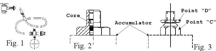
For accumulators rated for 3000 psi or less, use assembly RC-0185 as shown in figure 1.
Accumulators having gas valve as per figure 2.
- Remove gas valve guard and gas valve cap.
- Back gas chuck "T" handle all the way out (counterclockwise) before attaching charging assembly to accumulator gas valve.
- Close bleed valve.
- Attach swivel nut to gas valve and tighten (10-15 in. lbs.).
- Turn gas chuck "T" handle all the way down. This will depress core in gas valve and check pressure.
- To remove gauging assembly turn "T" handle all the way out on gas chuck (Figure 1), then open bleed valve.
- Hold gas valve from turning, loosen swivel nut, remove assembly.
- Replace gas valve cap (10-15 in lbs.) and valve guard.
Accumulators having gas valve as per figure 3.
- Remove gas valve guard and gas valve cap.
- Close bleed valve.
- Attach swivel nut to gas valve and tighten (10-15 in. lbs.).
- Hold gas valve at point "C" with one wrench while unscrewing hex nut at point "D" with a second wrench. This will open the poppet inside the gas valve. Turn 2-3 times and read pre-charge.
- With a wrench, tighten hex nut at point "D" to close internal poppet (5-8 ft. lbs.).
- Hold gas valve at point "C" with a wrench and remove swivel nut assembly.
- Replace gas cap and tighten (10-15 in. lbs.), and install gas valve guard.
Pre-Charging
Use and inert gas such as nitrogen for pre-charging accumulators.
If water pumped nitrogen is not available, oil-pumped nitrogen may be used.
Nitrogen source and all components must be rated for a pressure at least as high as the nitrogen source. It is strongly recommended that the nitrogen bottle used have a high pressure regulator.
Make sure nitrogen supply is shut off. Attach hose to nitrogen bottle. If accumulator has a gas valve as shown in figure 2, follow steps A through J and skip steps AA through HH. If accumulator has a gas valve as shown in figure 3, skip steps A through J and follow steps AA through HH.
Accumulator having gas valve as per figure 2.
| (A) |
Remove the gas valve guard and gas valve cap. |
| (B) |
Turn "T" handle on the nitrogen charging chuck all the way in the counterclockwise direction. Attach teh appropriate nitrogen charging chuck to the nitrogen charging valve. |
| (C) |
Close the bleed valve. |
| (D) |
Making sure not to loop or twist the hose, attach swivel nut to gas valve and tighten (10-15 in. lbs.). |
| (E) |
Turn gas chuck "T" handle all teh way down. This will depress core in gas valve. |
| (F) |
Crack open nitrogen bottle valve and slowly fill accumulator. Shut off when gauge indicates desired pre-charge. |
| (G) |
Let the pre-charge set for 10 to 15 minutes. This will allow the gas temperature to stabilize. If teh desired pre-charge is exceeded, close nitrogen bottle valve, then slowly open bleed valve. Do not reduce pre-charge by depressing valve core with a foreign object. High pressure may rupture rubber valve seat. |
| (H) |
When finished pre-charging accumulator, turn "T" handle all the way out on gas chuck, then open bleed valve. |
| (I) |
Hold gas valve to keep from turning, loosen swivel nut, remove assembly. |
| (J) |
Replace gas valve cap (10-15 in. lbs.) and valve guard. |
Accumulator having gas valve as per Figure 3.
| (AA) |
Remove gas valve guard and gas valve cap. |
| (BB) |
Close bleed valve and, making sure not to loop or twist the hose, attach swivel nut to gas valve and tighten (10-15 in. lbs.). |
| (CC) |
Hold gas valve at point "C" with one wrench while unscrewing hex nut at point "D" with a second wrench. This will open the poppet inside the gas valve. Note: four (4) turns will fully open the valve. |
| (DD) |
Crack open nitrogen bottle valve and slowly fill accumulator. Close nitrogen bottle valve when gauge indicates desired pre-charge. |
| (EE) |
Let the pre-charge set for 10-15 minutes. This will allow the gas temperature to stabilize. If the desired pre-charge is exceeded, close nitrogen bottle valve, slowly open bleed valve until desired pressure is reached. |
| (FF) |
With a wrench, tighten hex nut at point "D" to close internal poppet (5-8 ft. lbs.). |
| (GG) |
Hold gas valve at point "C" with wrench and remove swivel nut assembly. |
| (HH) |
When pre-charging has been completed, replace gas cap and tighten (10-15 in. lbs.), install gas valve guard. |
Testing the Diverter Valve
The following procedure is used to determine whether the diverter valve is operating correctly. Perform this test after teh accumulator is charged.
- Move the Ride Control switch to the OFF position.
- Place the bucket in the full DUMP position. Lift the front wheels off the ground by moving the lift control lever to the LOWER position.
NOTE: Make sure Auto Ride Switch is active (18" or above)
- Move the Ride Control switch to the ON position. The front wheels should lower to the ground.
If the wheels do not lower to the ground, the diverter valve spool has not shifted to the ON position. The following conditions are probable causes:
- The Ride Control Switch is failed.
- The solenoid coil on the diverter valve failed.
- The cartridge valve in the diverter valve failed.
- Blown fuse.
- The wire harness failed.
Road Test
| NOTE: |
For machines with heavy buckets, the nitrogen pressure may need to be increased in order to keep the accumulator bladder from puncturing or piston from striking the stop during normal roading while the Ride Control System is activated. Raising the nitrogen pressure will result in a stiffer ride. |
- Put a typical load in the bucket.
- Move the Ride Control Switch to the ON position.
- Drive the machine over a rough road surface.
If the bucket drops and does not bounce or the accumulator piston is striking the stop, the nitrogen pre-charge pressure must be increased.
NOTE: The Ride Control accumulators are rated up to 3000 psi.
- Refer to the "Nitrogen Charging Procedure". Increase the nitrogen pre-charge pressure by 50 psi and perform the road test again.
NOTE: Only add enough nitrogen in order to achieve a suitable ride for the machine's typical payload.
If you have any questions, please contact us.
Back to Parts Listing

Return To Home Page
Send comments to:
mpadilla@pwce.com
Copyright ©
2000 Paul Wever Construction Equipment Co., Inc./Paul Wever.
All rights reserved.
Last Revised: 06/20/01